Zybo Z7 HDMI Output
The Zybo Z7 has an HDMI output (TX) connector on the top-left of the board, which provides a simple 24-bits-per-pixel (8 red, 8 green, 8 blue) display output from the SoC.
Tip
Note that there is also an HDMI input (RX) connector on the top-right of the board. Ensure you plug the cable into the output and not this.
Images are displayed from a frame buffer in DDR, using a number of components in the FPGA logic to generate the HDMI/DVI graphics and associated signals. All the files mentioned below can be found in a repository on GitHub - you can download the latest version in a zip file from https://github.com/RTSYork/zybo-z7-hdmi/archive/master.zip. Either clone or download and unzip this repository to a location outside of your Vivado project directory before proceeding with the following steps. You only need to do this once, unless we update the files.
Adding HDMI output to a Vivado Design
In order to use the HDMI output, a number of Xilinx and Digilent IP cores need to be added to your block design, and connected up to the correct pins on the Zynq SoC package.
Referencing the repository for Digilent IP cores
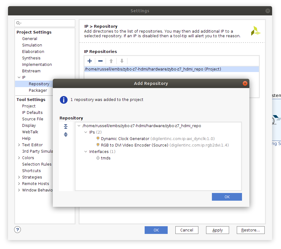
In Vivado, open the “Settings” screen (button in the top-left of the screen with the gear icon), expand the “IP” option under “Project Settings”, and select the “Repository” pane.
From here, click the + under “IP Repositories”, then select the hardware/zybo_z7_hdmi_repo folder from the downloaded HDMI repository. Vivado should find two IP cores and one interface definition in this repository (see the screenshot below).
If Vivado displays an error and can’t find any cores in the repository, and you extracted the files to within your Vivado project directory, try moving the repository to another folder outside your project.
Adding the IP cores using a Tcl script
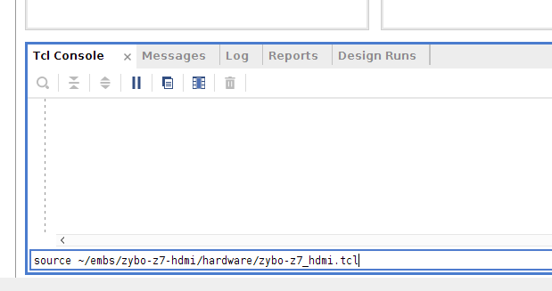
To automatically add the necessary cores to your project, set up their options and make the appropriate connections, a Tcl script is provided in the HDMI repository ( hardware/zybo_z7_hdmi.tcl ).
To run this script, you need to source it from the Vivado Tcl console (at the bottom of the block design window), using the command:source <path to repo>/hardware/zybo_z7_hdmi.tcl(as below).
Important
Ensure you already have a ‘ZYNQ7 Processing System’ block in your design before sourcing this script or it will fail.
After running this script, the following (currently unconnected) hierarchy should exist in your block design (use the +/- in the top left to expand and collapse a hierarchy block in Vivado).
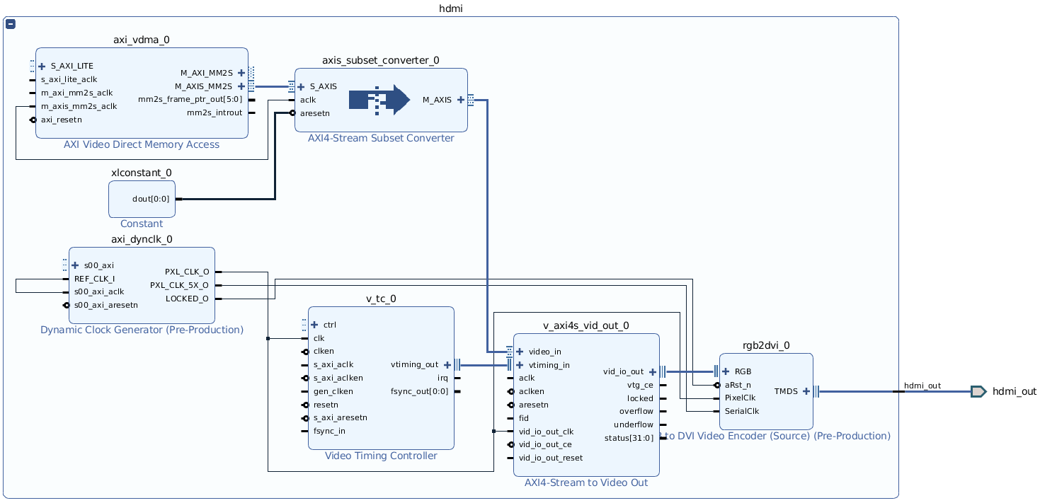
The HDMI output uses DMA to copy data directly from the DDR. To allow this, you will need a high-performance AXI slave port on the Zynq Processing System.
As we are using S_AXI_HP0 for HLS components, using S_AXI_HP1 for the HDMI will give the best performance, and avoid adding unnecessary additional bus logic to the FPGA fabric.
The script should enable this interface for you, but from this point on you will need to be careful in connection automation dialogs to ensure that the HDMI and HLS components use the correct interfaces.
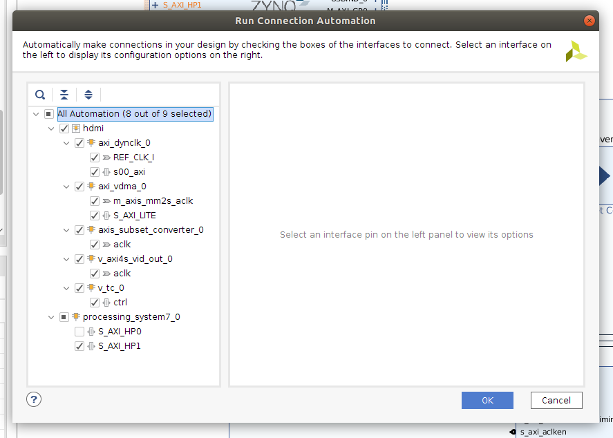
Next, click the “Run Connection Automation” prompt at the top of your block design to automatically connect up the AXI master and slave ports to the Processing System, and to assign addresses. The default values are usually sensible, but ensure that S_AXI_HP1 is selected as the processing_system7_0 interface (see screenshot).
If you already have a custom IP core in your design then you might be told some version of the critical warning:
Slave segment is not assigned into address space.
This is usually OK. It is telling you that your IP core is not able to acces the LOW_OCM address space inside the ARM SoC, which is not something that we are concerned about.
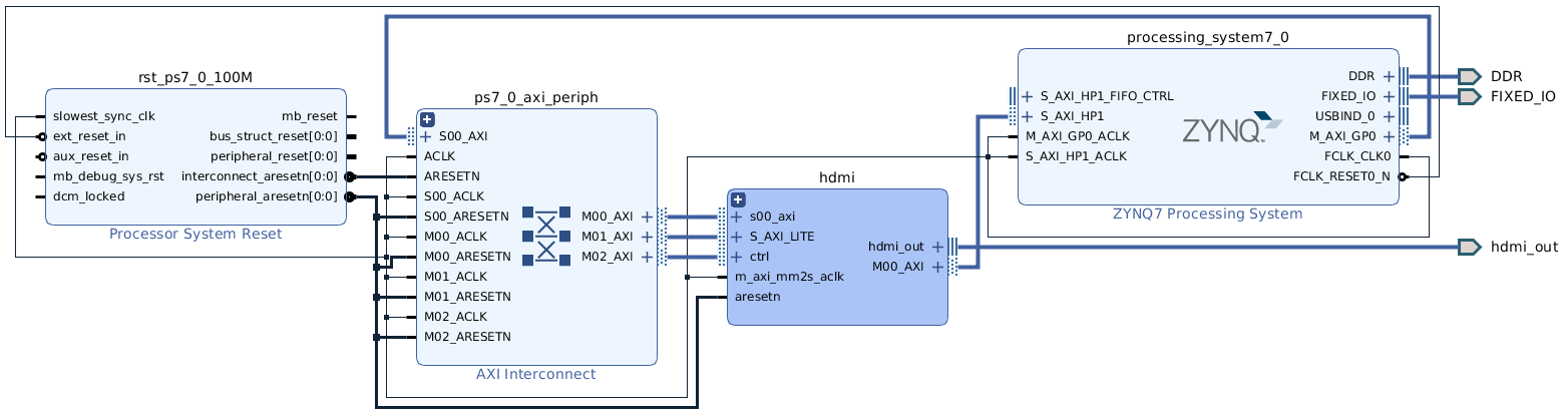
The resulting block design should look similar to the following. The tools should have also created an AXI SmartConnect IP within the HDMI block for the HDMI’s master interface, and assigned appropriate addresses for all the cores. This block design also has the LEDs, Buttons and Switches connected.
Adding the HDMI output pin constraints
To map the external HDMI pins from the block design to the physical pins of the SoC that connect to the HDMI TX port on the Zybo Z7 board, a set of pin constraints (from hardware/zybo_z7_hdmi.xdc ) needs to be added to your Vivado project.
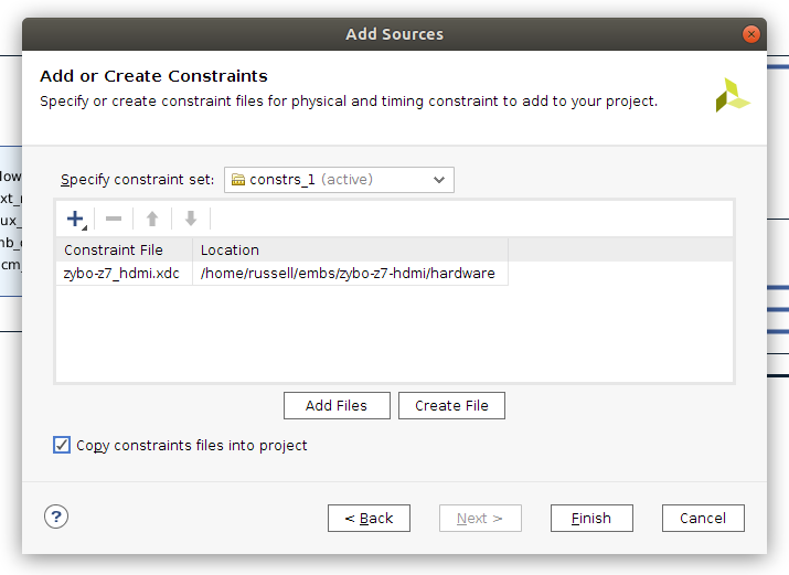
To do this, open your block design and select File, Add Sources. Choose “Add or create constraints” and click Next. Ensure “constrs_1” is selected as the constraint set, then click Add Files, and select hardware/zybo_z7_hdmi.xdc from the HDMI repository. Ensure that “Copy constraint files into project” is ticked, and click Finish.
The hardware design should now be ready for synthesis, implementation, and exporting to Vitis.
Using HDMI output in Vitis
The HDMI hardware uses two frame buffers in DDR. Data is stored in the frame buffer using 32 bits per pixel. Each colour component takes one byte, with the highest byte unused, followed by red, blue and green. This gives a pixel format of 0x00RRGGBB.
Remember to flush the caches after changing the frame buffer, so data is written back to DDR for the hardware to use. If writing the entire buffer, completely flushing the caches with Xil_DCacheFlush() will be more efficient than flushing a region, as the caches are significantly smaller than the frame buffer.
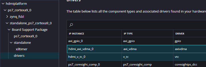
To get set up, import your new hardware as a new platform. The drivers for the Xilinx VDMA and VTC cores should be added to your System automatically. You can check this by opening the Settings -> vitis-comp.json file for your platform and looking at standalone_ps7_cortexa9_0 -> standalone -> drivers.
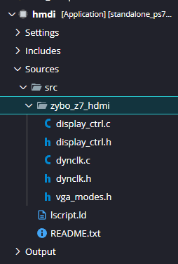
However additional code is required for the Digilent cores. Right click the src folder in your application project and select Import -> Folders.... Import the software/zybo_z7_hdmi/ folder.
Controlling the HDMI output from C
The HDMI display driver is set up in a similar way to other IP cores, using a struct of type DisplayCtrl(defined in zybo_z7_hdmi/display_ctrl.h ). The functions in display_ctrl.h can be used to initialise the display controller, start and stop the output, change the current frame buffer, and set the output resolution.
These functions are documented in the library source code, and hdmi_example.c shows how to set up the output and display a basic gradient on the screen.
Possible output resolutions are in zybo_z7_hdmi/vga_modes.h - the widescreen monitors in the hardware labs work well with a 1440x900 resolution (this is fine for EMBS).
Higher resolutions than this are possible (e.g. 1680x1050), but require the master interface of the AXI VDMA core to be clocked faster than default (125MHz should work).
Smooth frame transitions
When creating animations, smooth transitions between frames can be achieved by writing to the back buffer (the currentlyinactiveframe), then switching to it with DisplayChangeFrame() during the vertical blanking interval.
This function will return immediately, but the DisplayWaitForSync() function can then be used to synchronise with the frame output, so the active buffer is never directly written to. This function will block until the frame specified with DisplayChangeFrame() is actually being shown.
An example of this can be seen in hdmi_example_anim.c.
Using the HDMI over the VLAB
Obviously it is easier to test the HDMI by directly connecting the board to a monitor, but it is also possible to observe the output over the VLAB. Connect the VLAB, program the bitfile and get your application running. Then in another terminal run a second VLAB command:
./vlab.py -k yourkeyfile.vlabkey --captureIn other words, the exact same command that you used to connect, with --capture on the end. If everything works, the result will be a file capture_xxxxxxxx_xxxxxx.jpg in the current directory. This takes a few seconds, so you can only usefully observe static images, but it should still be useful for testing.
By default the file is named capture_xxxxxxxx_xxxxxx.jpg; pass -o myframe.jpg to choose your own filename. The capture assumes the HDMI VDMA peripheral is at the default address of 0x43000000 (correct for the standard HDMI example). If your block design places it elsewhere, give its base address (from the Vivado Address Editor) with --vdma:
./vlab.py -k yourkeyfile.vlabkey --capture --vdma 0x43000000Technical details
Fundamentally this capture process is just using the xsdb debugging interface to read the framebuffer directly out of DDR memory. It assumes the HDMI VDMA hardware is at the default address of 0x43000000 (overridable with --vdma, as above), so it first reads from that to find out where your frame buffers are in RAM, then goes and reads that.
However, reading RAM this way is slow. Pulling the entire frame buffer over the debugging interface takes more than 10 seconds. So this uses an off-the-shelf C implementation of a JPEG encoder, compiled with a custom linker script to use the following memory map:
 * Memory map (top 3MB of 512MB DDR):
 *   0x00000000 - 0x1FCFFFFF  Your memory (Untouched)
 *   0x1FD00000 - 0x1FDFEFFF  Stack (~1MB)
 *   0x1FDFF000 - 0x1FDFFFFF  Shared params, flags (4KB)
 *   0x1FE00000 - 0x1FEFFFFF  JPEG output buffer (~1MB)
 *   0x1FF00000 - 0x1FFFFFFF  Capture daemon code + data (~1MB)
The capture process sends this elf to memory (clobbering the top ~3MB of DDR RAM) and then sets the second ARM core to execute it. That core dutifully makes a jpeg of the framebuffer which is far smaller than the raw data, which the script pulls back. This whole complex process is around three times faster overall. Embedded systems are cool.
Accordingly, this capture process will interfere with your application if you either use the second core, or use the top ~3MB of DDR. Otherwise it should be entirely transparent to your application.