Practical 5 - Using FreeRTOS
In the previous practical we deployed an HLS component and accessed it from bare metal C code. In this practical we will introduce FreeRTOS, a lightweight real-time operating system, and learn how to use its multitasking and inter-task communication features. By the end of this practical you will:
- Understand how to create and manage FreeRTOS tasks
- Use semaphores to signal between tasks
- Use queues to pass data between tasks
- And have a bit more practice with creating custom hardware
Why Use an RTOS?
As we saw previously, when you have to do lots of things at the same time (like taking input from the user and the Ethernet) we end up writing a state machine in the main loop. Every activity must be interleaved manually, and the code becomes hard to read and maintain. With an RTOS like FreeRTOS, each activity becomes an independent task with its own execution flow. The scheduler handles switching between tasks, and you can use queues and semaphores to communicate between them cleanly. The result is code that’s easier to write, understand, and debug.
Part 1: A Simple Random Number Generator in HLS
We’re going to build a reaction time tester, so we are going to need something to create random time delays. Yes, you could just use the rand() function in the C standard library, but we have a big chunk of custom hardware so we’re going to use that instead. Task 1 is to create a hardware random number generator using a Linear Feedback Shift Register (LFSR). An LFSR is a shift register whose input bit is a linear function of its previous state, and if that function is well-chosen then you get a decently approximative pseudo-random sequence.
Create a new Vitis HLS project with the toplevel that we have used previously. You can take the code from Wikipedia to actually implement the LFSR (I’ve taken a copy here just in case).
LFSR code from Wikipedia
#include <stdint.h>
unsigned lfsr_fib(void)
{
    uint16_t start_state = 0xACE1u;  /* Any nonzero start state will work. */
    uint16_t lfsr = start_state;
    uint16_t bit;                    /* Must be 16-bit to allow bit<<15 later in the code */
    unsigned period = 0;

    do
    {   /* taps: 16 14 13 11; feedback polynomial: x^16 + x^14 + x^13 + x^11 + 1 */
        bit = ((lfsr >> 0) ^ (lfsr >> 2) ^ (lfsr >> 3) ^ (lfsr >> 5)) & 1u;
        lfsr = (lfsr >> 1) | (bit << 15);
        ++period;
    }
    while (lfsr != start_state);

    return period;
}
This code is written to keep looping until the output equals the starting state. Instead make the component return the next pseudo-random 16-bit value. If you aren’t as familiar with C, then you can use the static keyword to ensure that lfsr retains its value between calls.
Task
Create a testbench that calls the toplevel function multiple times and prints the sequence of random numbers. Verify that you get different values each time (they should not repeat for 65535 calls). Synthesise your design once you’re happy with it.
Part 2: Deploying the Random Number Generator and Preparing hardware for FreeRTOS
We now need to do two things:
- Create a timer which FreeRTOS is going to use later.
- Add our IP core into the Vivado block design.
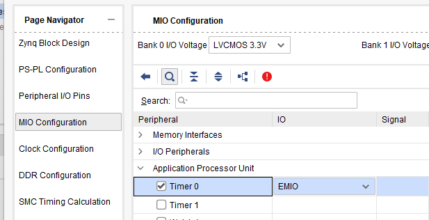
First, adding the timer is easy. In Vivado, open your Block Design and double click the ZYNQ7 Processing System block. This will open a configuration dialogue. Under MIO Configuration find Application Processor Unit, tick Timer 0 and set it to EMIO.
When you OK out, you will see that a few new outputs appear on the right side of the Zynq block (TTC0_WAVE0_OUT etc.). We don’t need these, but they show us that the timer peripheral is now activated.
Now deploy your LFSR IP core to your Vivado design following the same process as in Practical 4:
- Export RTL from HLS (Solution → Export RTL)
- In Vivado, add the IP repository and add your new IP to the block design
- Also add the LEDs and Buttons in the way that we did way back in practical 1
- Use Connection Automation to wire it up
- Generate Bitstream and Export Hardware
You should now have a hardware platform with your random number generator, buttons, and LEDs, all ready to use.
Part 3: Setting Up FreeRTOS
The following two links may be useful going forward:
- FreeRTOS Reference — Detailed API reference for FreeRTOS on the Zynq
- FreeRTOS Official Documentation — Complete API reference
Now we’ll create a FreeRTOS project to use our hardware.
- In Vitis, create a new Application Project
- Select your hardware platform (the one with your LFSR IP)
- Give it a sensible name like
reaction_game - Important: When selecting the Domain, click “Create new…” and set:
- Name: something sensible like
freertosbut can be anything - Operating System:
freertos - Processor:
ps7_cortexa9_0
- Name: something sensible like
Your First FreeRTOS Program
Let’s start with a simple program that creates two tasks. Create a file called main.c:
main.c
#include <stdio.h>
#include "xparameters.h"
#include <xgpio.h>
#include "xil_printf.h"

#include "FreeRTOS.h"
#include "task.h"

#define THREAD_STACKSIZE 1024

// GPIO instance for LEDs and buttons
XGpio Gpio;

// Task function prototypes
void led_task(void *p);
void button_task(void *p);

int main() {
    // Initialise GPIO
    XGpio_Initialize(&Gpio, XPAR_GPIO_0_BASEADDR);
    XGpio_SetDataDirection(&Gpio, 1, 0x00);  // LEDs are outputs
    XGpio_SetDataDirection(&Gpio, 2, 0xFF);  // Buttons are inputs

    xil_printf("Starting FreeRTOS...\r\n");

    // Create tasks
    xTaskCreate(led_task, "led_task", THREAD_STACKSIZE, NULL, 1, NULL);
    xTaskCreate(button_task, "button_task", THREAD_STACKSIZE, NULL, 1, NULL);

    // Start the scheduler - this never returns
    vTaskStartScheduler();

    return 0;
}

void led_task(void *p) {
    int led_state = 0;
    while (1) {
        XGpio_DiscreteWrite(&Gpio, 1, led_state);
        led_state = (led_state + 1) % 16;  // Cycle through LED patterns
        vTaskDelay(500 / portTICK_RATE_MS);  // Delay 500ms
    }
}

void button_task(void *p) {
    while (1) {
        int buttons = XGpio_DiscreteRead(&Gpio, 2);
        if (buttons != 0) {
            xil_printf("Button pressed: %d\r\n", buttons);
        }
        vTaskDelay(100 / portTICK_RATE_MS);  // Check every 100ms
    }
}
Build and run this program. You should see the LEDs cycling through patterns while the button task independently reports button presses. Notice how each task has its own while(1) loop meaning that they run concurrently without you having to manually interleave them.
xTaskCreatecreates a new task. Parameters are: function, name, stack size, parameters, priority, and handle.vTaskDelaypauses the current task for a specified time, allowing other tasks to run.vTaskStartSchedulerstarts the FreeRTOS scheduler — after this call, your tasks begin executing.- Each task is an infinite loop that does its job and then delays, giving other tasks a chance to run.
Part 4: Inter-Task Communication
FreeRTOS provides several mechanisms for tasks to communicate:
- Semaphores: For signaling events between tasks
- Queues: For passing data between tasks
- Mutexes: For protecting shared resources
Binary Semaphores
A binary semaphore is a thread-safe flag that one task can ‘give’ and another can ’take’. If a task tries to ’take’ a semaphore that hasn’t been ‘given’, it blocks (waits) until the semaphore becomes available. For example:
#include "semphr.h"

SemaphoreHandle_t mySemaphore;

// In main(), before creating tasks:
mySemaphore = xSemaphoreCreateBinary();

// In one task (the signaler):
xSemaphoreGive(mySemaphore);

// In another task (the waiter):
if (xSemaphoreTake(mySemaphore, portMAX_DELAY) == pdTRUE) {
    // Semaphore was given - do something
}
Queues
Queues allow tasks to send structured data to each other. They’re thread-safe and can hold multiple items.
#include "queue.h"

QueueHandle_t myQueue;

// In main:
myQueue = xQueueCreate(10, sizeof(int));  // Queue of 10 integers

// Sending task:
int value = 42;
xQueueSend(myQueue, &value, portMAX_DELAY);

// Receiving task:
int received;
if (xQueueReceive(myQueue, &received, portMAX_DELAY) == pdTRUE) {
    // received now contains 42
}
Part 5: The Reaction Time Game
Now let’s build our reaction time tester. The system will work as follows:
- Wait a random amount of time (~1-5 seconds)
- An LED lights up
- The player must press the corresponding button as fast as possible
- The system measures and displays the reaction time
- Repeat for multiple rounds
To program this, use three tasks:
game_task: Controls the game flow, uses the hardware RNG for random delaysled_task: Waits for signals to turn LEDs on/offbutton_task: Monitors buttons and signals when one is pressed
Task Priorities
You are going to have to give your tasks a priority. If you have two tasks at the same priority, then FreeRTOS will not forcibly suspend a task and switch between them (like Windows / Linux / macOS would). FreeRTOS is always running the task which is of the highest priority (largest number) and is not otherwise blocked or waiting.
Task
Build the reaction time game using the task structure above and with suitable intertask communications primitives.
Bare Metal Comparison
To appreciate what FreeRTOS gives you, consider how you would have to program the bare metal version:
Bare metal version
int main() {
    int state = STATE_WAITING;
    int delay_remaining = 0;
    int target_led = 0;
    uint32_t led_on_time = 0;

    while (1) {
        switch (state) {
            case STATE_WAITING:
                delay_remaining = get_random_delay();
                state = STATE_COUNTDOWN;
                break;

            case STATE_COUNTDOWN:
                // Delay but also keep checking buttons...
                if (/* time elapsed */) {
                    state = STATE_LED_ON;
                }
                if (/* button pressed */) {
                    // Too early -> handle with some state...
                }
                break;

            case STATE_LED_ON:
                // Turn on LED, start timing, keep checking buttons...
                break;

            // ... lots more ...
So you can see two things:
- The code is a lot more complex to follow and update. You’d probably find you need to draw out a state machine diagram to follow everything if you wanted to add two-player support or other features.
- It is much harder to understand the worst-case response time (i.e. the accuracy of the tester) because you need to account for all system states, the transitions between them, and then the actual timings of the system functions.
These are the fundamental building blocks of RTOS programming. In the next practical, we’ll combine these concepts with networking and a more complex hardware accelerator.