Practical 1b - ARM Software
We have already seen in Practical 1 how to build an example system and get some basic software running. In this practical we are going to learn two important things.
- How to write some slightly more complex software.
- How to go back and adjust our hardware design to add new features.
Open Vitis. You should still have in your workspace the platform and application project from Practical 1.
Task 1: Buttons and LEDs
Recall that in our Vivado hardware design we added a GPIO controller to connect to buttons and LEDs. Let’s now write code to use it. Xilinx helpfully provide code examples for all the “blocks” that appear in Vivado so instead of starting from scratch let’s see how to use those.
Expand your platform, and go into
Settings → vitis-comp.json.This shows you lots of details about your hardware platform that you exported from Vivado. On the left click on
<platform name> → ps7_cortexa9_0 → standalone_ps7_cortexa9_0 → Board Support Package → drivers.This shows you all the cores in your design - basically the blocks in your Vivado block diagram. You should see
axi_gpio_0which if you recall from practical 1 is the GPIO controller to connect to IO.Click Import Examples, tick
xgpio_exampleand OK. Vitis will pull you in an example which uses the GPIO.To do this, it creates a new Application Project called
xgpio_example_1_systemBuild this project (select it in the Flows panel and select Build) and then run it.
Observe that it makes an LED flash. Oh happy days.
Familiarise yourself with the code in the example. It is only one source file (xgpio_example.c) and most of that file is comments.
Task
Your task is to modify this code so that instead of flashing the LED, it copies the value of the Buttons to the LEDs (i.e so the LEDs are normally off, but if you press a button the corresponding LED lights).
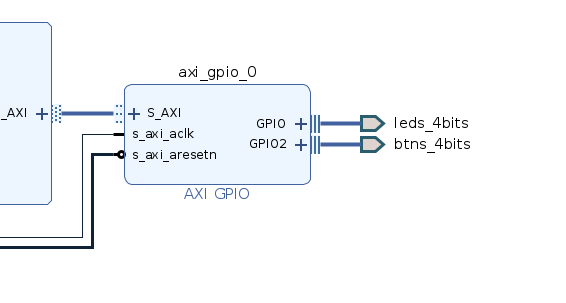
You will need to know two things. If you followed the instructions in practical 1 carefully, the LEDs are on channel 1 of the GPIO core, the Buttons are on Channel 2. We can check this in Vivado:
XGpio_SetDataDirection sets the direction of a channel. The third argument should be 0 for outputs and all 0xFF for inputs.
If you’re having trouble figuring things out, speak to Ian. Also, if the sight of C is scaring you, don’t panic. We won’t need much more complicated than this.
Task 2: Serial Calculator
Now we are going to learn to interact with the user. Read the “Low-level UART (Serial) Functions” section of the Software API to learn how to use the UART.
Task
Write an application which implements a simple serial line calculator. The interaction with the user is:
- The calculator waits for a number from the user which will be entered with the number keys followed by the space bar.
- The user enters either a
+(plus)-(minus)*(multiply) or/(divide) symbol. - The user enters a second number as in step 1.
- The user enters equals
= - The result of the calculation is printed to the user.
Task 3: Extending our Hardware
Our current design lets us access the LEDs and Buttons. Let’s extend it to also access the Switches and the RGB LED. Go back to our Vivado project and Open Block Diagram. Then in Board, double click 2 RGB LEDs, then OK, then 4 Switches, then OK. The AXI GPIO component can only handle up to 2 connections, so it has created us a second one.
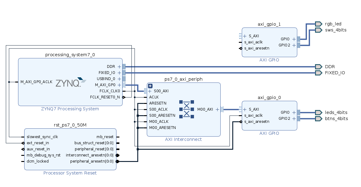
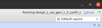
Run Connection Automation, to have Vivado wire it up for us. Once wired up, Generate Bitstream. This will be faster than last time because we’ve only changed a small part of our design. It will still take ages, go get a coffee.
Once done, we need to re-export the new hardware. File → Export → Export Hardware, and click through, answering yes to overwrite your old one.
Back in Vitis, we need to tell it to re-read the hardware details. In the explorer panel, click your hardware platform (basicIO_platform) and select Settings → vitis-comp.json then Switch / re-read XSA and select your newly exported hardware. Vitis will pull in the new design. Now if you look under drivers you can see Vitis knows there are two GPIO cores:
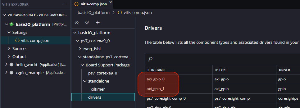
The xgpio_example application project will still work for your updated hardware.
Task
Your task is to now extend that application to also read from the Switches and send those values to the RGB LED.
Hints:
- Line 110 creates a variable called
Gpiowhich is used to talk to the first GPIO core. You will need to create another such variable. - You will also need to initialise this variable with
XGpio_Initialize. - The first was initialised with
XGPIO_AXI_BASEADDRESS, which if we look on line 58 is really justXPAR_GPIO_0_BASEADDR. - Since we added a second GPIO core, Vitis nicely created us a
XPAR_GPIO_1_BASEADDR, so use that.